HANNZ MOTROLproduct
INDXIA
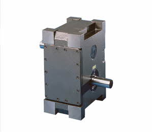
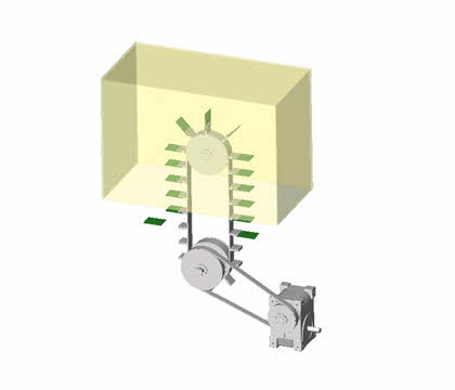
Parallel index is a dividing device of the parallel equipment.
This device is in parallel with the input and output axes that small number of stops including 1, 2, and 3 stops as “the most ideal parallel cam” for the straight delivery of conveyor.
When the two plate cams in the input axis rotate, the output axis starts rotating with the cam follower. When comparing with the Geneva cam that are in parallel with the input and output axes,
Parallel index is more outstanding in terms of the dynamic features, accuracy, and load characteristics on the division.
Characteristics of the product
-
More useful in condition of
high mechanical efficiency of power transmission,
Low Backlash, and stable revolve to be needed. -
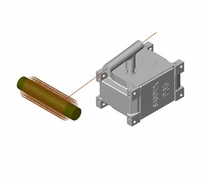
Use Hannz Motrol unique constant
velocity cam curve,
Realized high precision and high torque.
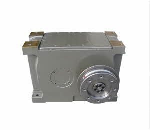
Option Specifications
HP series model supports
the torque shields and
worm reducer as an option
< Installed with torque shield >
Code overview
Product code consists of the size, number of stop, index period, cam curve, cam rotation direction, input-output axis figure, mounting position and special specifications.
It is needed to determine accurate product information by suggesting usage requirements clearly.
Information such as RPM and demand precision is required. please contact to the sales department of our company if you use Indexing drive for the first time.
| Item | Example | Specific explanation |
|---|---|---|
| Format | HP |
Means the type of device |
| Size | 200K |
Means the distance between input and output axis (mm) - As for HP type model, 100 to 400mm are prepared |
| Number of division | 01 |
Means the number of stop per output axis for each rotation of the input axis - Up to 8 stops are available depending on the specifications of dwell of cam |
| Index period | 27 |
Means the angle needed for the 1st stop on the output axis
- Dividing angle is determine by the ratio of operating time: stoppage time (total tech time) |
| Cam code curve | 2 |
[2] MS deformed pattern angle curve – standard specification curve
|
| Cam rotation direction | A |
Means rotate direction of output shaft, which following for rotate direction of input shaft - If interlocked with device such as other plate cam that normal or opposite direction of rotation in the driving force are not available, Please care has to be taken when selecting the direction. |
| Number of dwell | blank |
No indication: 1 dwell (standard one)
|
| Specifications of the output axis | S |
S : Standard (Standard specifications)
|
| Specification of the input axis | 2 |
1: Input axis in the T-side[R1] input on the T side of reducer 2 : Input axis in the U-side[R2] input on the U side of reducer 3 : Input axis in both sides[R3] input on both sides of reducer |
| Mounting holes | VW |
VW : tapped hole on V and W surfaces |
| Mounting position | 1~6 |
- GL : Ground Level
|
| Special specifications | /X |
Indicate whether there is special specification.
|