HANNZ MOTROLproduct
INDXIA
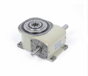
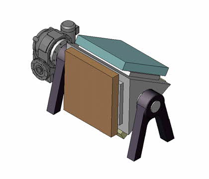
INDXIA HA series are fixed hollow axis-type indexing drive which integrates compact flat housing and driving parts. Therefore, more compact facility is to be organized.
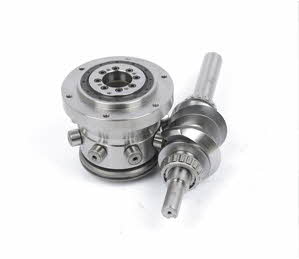
The strength of unique structure of roller gear cam of our company is to be maintained but improved with convenience of users.
Characteristics of the product
-
7 types of standardized distance between axes(Input and output) from 70 to 330 mm
-
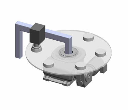
As standard, a fixed hollow axis is mounted on the center of output flange
-
Wide range of the number of stops from 2 to 32
-
Available to install timing cam and sensor on the input axis
-
High Rigidity hollow output flange
-
Available to install torque shield on the output axis
-
Compact design with flat type housing
-
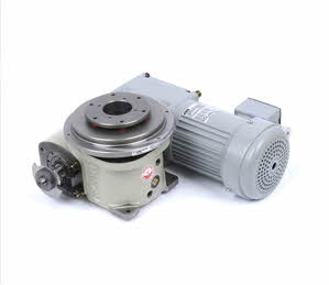
Available to install Geared Motor on the input shaft.
Code overview
Product code consists of the size, number of stop, index period, cam curve, cam rotation direction, input-output axis figure, mounting position, and special specifications. It is needed to determine accurate product information by suggesting usage requirements clearly. Information such as RPM and demand precision is required. Please contact to the sales department of our company if you use Indexing drive for the first time.
| Item | Example | Specific explanation |
|---|---|---|
| Format | HA |
Means the type of device
|
| Size | 090 |
Means the distance between input axes and output axis (mm) - As for HA type model, 70 to 450mm are prepared. |
| Number of division | 08 |
Means the number of stop per output axis for each rotation of the input axis - Up to 48 stops are available depending on the specifications of dwell of cam |
| Index period | 27 |
Means the angle needed for the 1st stop on the cam of output axis
- Dividing angle is determined by the ratio of operating time: stoppage time (total tech time)
|
| Cam curve | 7 |
SMS-3 Modified Sine– standards curve
- Other cam curves and order-made specifications need to be separately inquired. |
| Direction of Cam rotation | R |
R : Output rotates counter-clock wise when the input rotates in a normal direction
- If regular or opposite rotation of the driving source are not possible after applied to the interlocking devices such as a cases of attaching the plate cam, a care has to be taken on selection of rotation direction. |
| Number of dwell | blank |
No indication: 1 dwell (standard one)
|
| Specifications of the output axis | S |
S : Standard (Standard specifications)
|
| Option specifications | M |
M : Type installed with geared motor |
| Specification of the input axis | 3 |
1: Input axis in the T-surface only
|
| Mounting holes | VW |
VW : tapped hole on V and W surfaces |
| Mounting position | 1~5 |
- GL : Ground level
|
| Special specifications | /X |
Indicate whether there is special specification.
|